In the previous step, we finally got our first image. But unfortunately, it was broken - the polygons were drawn in the incorrect order. I omit the depth buffer management to make the complex Vulkan a little bit simpler. Also, I wanted to show how to change the existing renderer. With all the knowledge we have, it should be quite simple.
As you may know, the depth buffer is a special image where the GPU writes the depth information when rasterizes polygons. In this step, we’ll create that image and adjust the pipeline to use it.
The best way to see what was changed is to compare this and previous steps in git. Github allows you to do it directly in a browser. You can check it here. And these are the steps we need:
- create a depth image.
- update the render pass.
- set a new depth stencil state in the pipeline.
- update the framebuffers.
- update
drawfunction. - clean.
As usual, we’ll examine all these changes one by one.
Depth image
Although an image in Vulkan is much more complex than the buffer, their creation is still very similar. First, we need to create an image object, then allocate memory for it, and finally bind them together.
A depth buffer is a common thing, so its management is done in the vulkan_base workspace. In the function create_depth_buffer we create the depth image by setting the following parameters for the ash::vk::vk::ImageCreateInfo structure:
image_type = ash::vk::ImageType::TYPE_2D- depth image is a 2D image.format = depth_format- the format of the depth image. We can’t just take any we like, but we need to query for a format supported on hardware. Luckily we already did this in step 1. One more time, here’s a to the vulkan_base::get_depth_format function.extent = extent- the depth image dimensions. We use the same dimensions as our window size.mip_levels = 1- we are not using mipmapping for the depth image.array_layers = 1- we are not using arrays of images for the depth image.samples = ash::vk::SampleCountFlags::TYPE_1- we are not using multisampling for the depth image.tiling = ash::vk::ImageTiling::OPTIMAL- according to the Specification, an image with a depth/stencil format can’t have a linear tiling. And in the aforementionedvulkan_base::get_depth_format, we checked if our format supports the optimal tiling.usage = ash::vk::ImageUsageFlags::DEPTH_STENCIL_ATTACHMENT- the depth image will be used as the depth attachment.sharing_mode = ash::vk::SharingMode::EXCLUSIVE- this property relates to multiple queues usage. Since we are using a single queue, we mark the depth image as exclusive for it.initial_layout = ash::vk::ImageLayout::UNDEFINED- when an image is created its initial layout must beash::vk::ImageLayout::UNDEFINEDorash::vk::ImageLayout::PREINITIALIZED. We do not need to preinitialize the depth image.
The image object is created with the ash::Device::create_image function.
Next, we need to allocate and bind a memory in the same way we did for buffers:
- get memory requirements.
- call the
gpu_allocator::Allocator::allocatehelper function. - call the
ash::Device::bind_image_memoryfunction.
Obviously, the size of the memory will be different depending on the chosen format and dimensions of the image.
After that, we need to create the image view for the depth image because Vulkan requires a view for some commands. We already created image views for the swapchain images, so if you don’t remember why we need them, refer to the previous step. As a reminder, a view is created with the ash::Device::create_image_view function;
Similar to buffers, the image-related data is stored in an MemImage structure.
The depth image creation procedure resides in the vulkan_base::VulkanBase::resize function - we need to create a new image object and allocate the memory whenever dimensions are changed. Of course, the old image and memory should be cleared.
Render pass
In the previous step, we discussed what is a render pass and why we need it. We discussed that attachment types should be declared upfront, and since the depth buffer is an attachment, we need to change the render pass to use this new information. In the teapot::create_render_pass function we add the new depth attachment description with the following parameters:
format = depth_format- same as the image format.samples = ash::vk::SampleCountFlags::TYPE_1- no multisampling.load_op = ash::vk::AttachmentLoadOp::CLEAR- when we begin the render pass, the depth attachment should be cleared (the clear value is set in theash::Device::cmd_begin_render_passfunction, see later).store_op = ash::vk::AttachmentStoreOp::DONT_CARE- after the render pass we don’t care about the contents of the depth image.stencil_load_op = ash::vk::AttachmentLoadOp::DONT_CARE- we’re not using stenciling.stencil_store_op = ash::vk::AttachmentStoreOp::DONT_CARE- we’re not using stenciling.initial_layout = ash::vk::ImageLayout::UNDEFINED- we don’t care about the initial layout. The API will implicitly transition the memory to the appropriate layout.final_layout = ash::vk::ImageLayout::DEPTH_STENCIL_ATTACHMENT_OPTIMAL- actually, we do not care which layout the depth image is in after the render pass ends. But according to the Specification, it can not haveash::vk::ImageLayout::UNDEFINED, so we have to set some other layout. It could beash::vk::ImageLayout::GENERAL, for example. But since during the subpass (see later), the depth image must have theash::vk::ImageLayout::DEPTH_STENCIL_ATTACHMENT_OPTIMALlayout, we leave the final layout the same to avoid unnecessary implicit transition.
After the description is done, we refer to it by providing the attachment index to the ash::vk::AttachmentReference structure. Additionally, we set the layout in which the image should have during the subpass - ash::vk::ImageLayout::DEPTH_STENCIL_ATTACHMENT_OPTIMAL.
NOTE: a render pass and a depth buffer is perfect example of where a tiled GPU architecture shines. At the beginning of the render pass, a small but fast on-tile memory will be initialized to some value (
ash::vk::AttachmentLoadOp::CLEAR), during the render pass, reading and writing into it will be very fast, much faster if it would be accessed from the global memory, and finally, at the end of the render pass, the results will be discarded (ash::vk::AttachmentStoreOp::DONT_CARE), i.e. the access to global memory is completely avoided.
Depth Stencil State
The next change is in the teapot::create_pipelines function. This time, instead of an empty state we provide ash::vk::PipelineDepthStencilStateCreateInfo to the pipelines create function with the following parameters:
depth_test_enable = true- we want use depth testing.depth_write_enable = true- we want to update depth buffer.depth_compare_op = ash::vk::CompareOp::LESS_OR_EQUAL- if the depth of the current fragment is less or equal to the depth in the depth buffer, the test is passed, the new fragment calculates its value, and the new depth is written to the depth buffer. A GPU can use depth testing for early-Z test - if the test fails, no fragment shader is executed, which saves a lot of time. That’s why it’s recommended to draw sorted geometry from front to back, if possible.
Framebuffer
In the render pass creation, we specified two attachment types for color and depth. In other words, we just declared the types of images we want to use with the render pass. Recall that we set the real attachments with a Framebuffer object. In the function teapot::create_framebuffers, we add a new depth image view. To enable multi-buffering, we use more than one color attachment (swapchain images), and each framebuffer refers to a separate view. But we don’t need multiple depth buffers because they are not presented to the screen, and as soon as we draw a scene, we can start to reuse memory. That’s why there’s the same depth image view for all framebuffers.
Drawing
The only thing that needs to be changed in the vulkan_draw::draw function is how we begin the render pass. In the function vulkan_draw::begin_render_pass we need to set clear values for both our attachments (because in render pass we specified that we want to clean them by providing ash::vk::AttachmentLoadOp::CLEAR parameter to both descriptions). For the color attachment, we leave the clear color as it was before, and for the depth attachment, we specify ash::vk::ClearDepthStencilValue with the depth equal to 1.0. And that’s it - all other code doesn’t need to be changed.
Clean
In the function vulkan_base::clean, we destroy the depth image by destroying the image object, image view object, and freeing the memory.
Conclusion
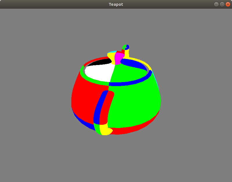
Congratulations! With all the changes applied, we finally can see the correct teapot:

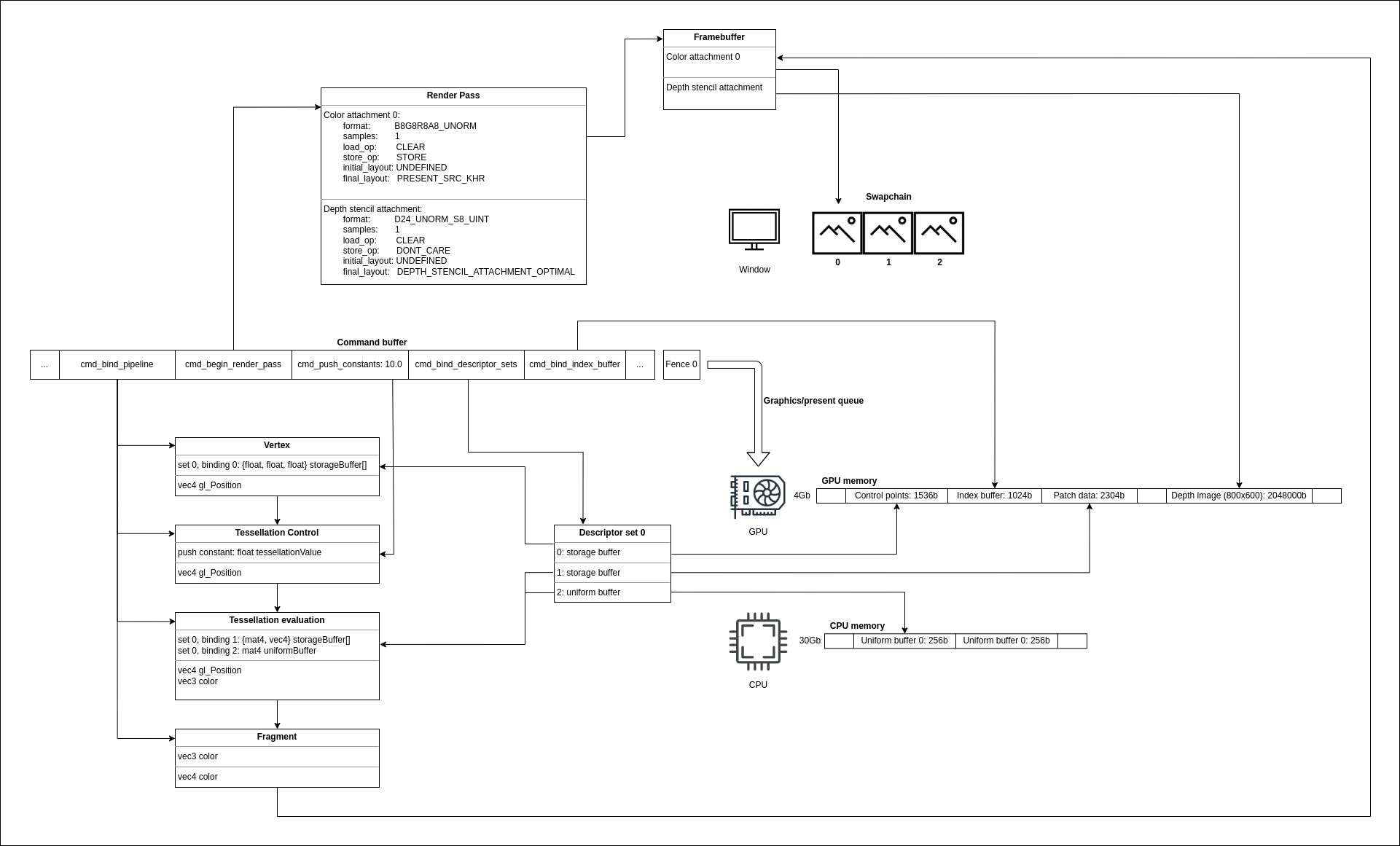
On the updated diagram we can see where the depth buffer resides in the application:

The source code for this step is here.
You can subscribe to my Twitter account to be notified when the new post is out or for comments and suggestions. If you found a bug, please raise an issue. If you have a question, you can start a discussion here.