We have 4 shaders we created in the previous step, but these are useless until we feed GPU data. Let’s look at the picture to recall which kind of resources we need.
- Introduction
- Shaders
- Resources
- Pipelines
- Swapchain
- Drawing
- Depth Buffer

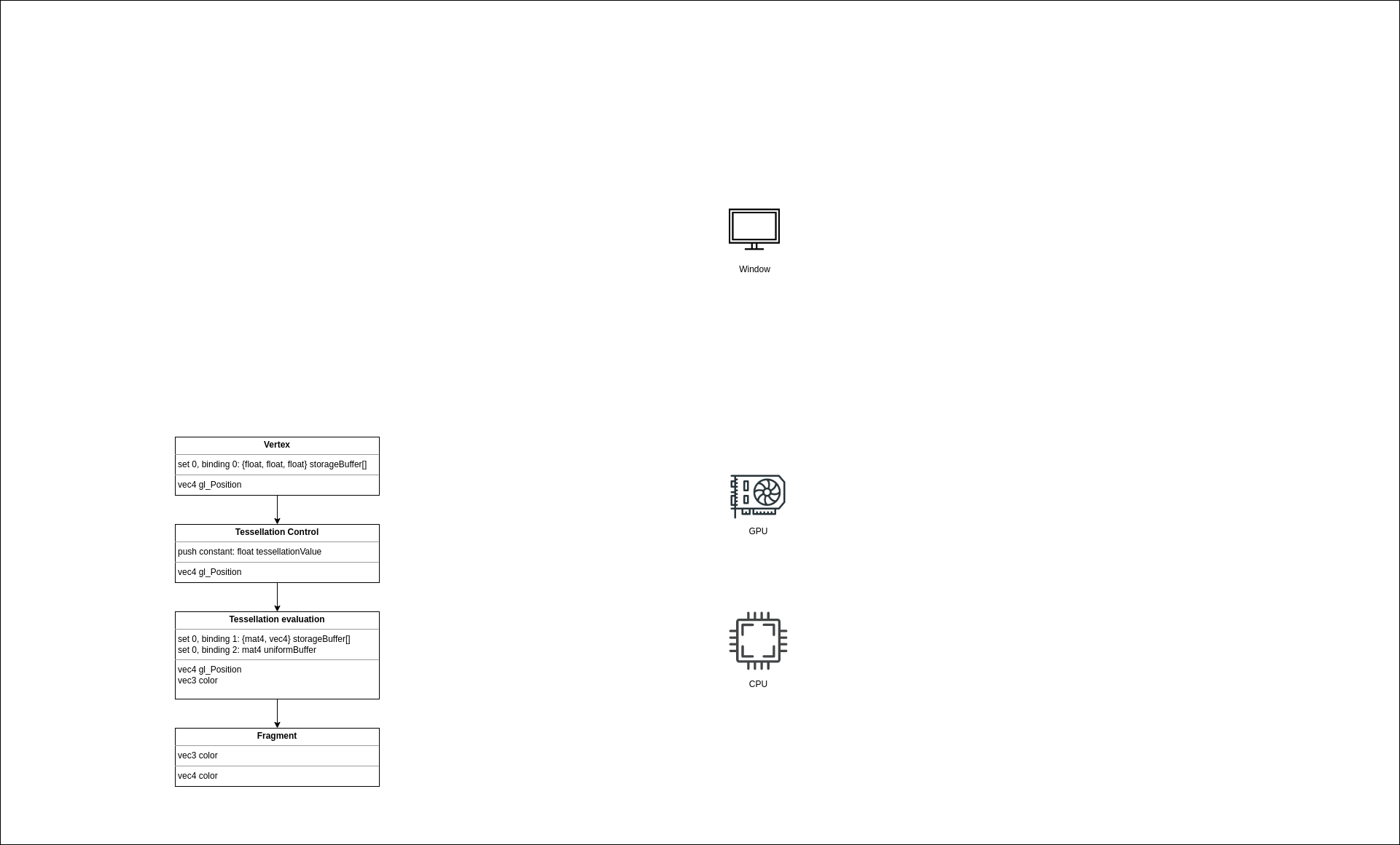
The upper part for every block shows input parameters, and the lower part shows output, i.e., the result of a shader.
Let’s start with the vertex shader. We see that the shader reads a list of control points in the set 0 at binding 0. We left sets and bindings for later. There’re multiple ways to supply data to a shader and we’ll pass it via ControlPointBuffer which is a read-only storage buffer that holds an array of ControlPoint structs. I decided to use a storage buffer instead of a vertex buffer because it’s simpler. For a vertex buffer, a special input assembler struct is needed that describes how a vertex is laid out in memory. With storage buffer, we don’t need that. Besides that, there’s no difference in performance. So let’s create it.
NOTE: For the application, we need only 3-component vectors for position and the logical question would be why not write directly
vec3 data[]? By weird packing and alignment rulesvec3andvec4are aligned as itsvec4. So samplingbuf[i]will return a value with an alignment equal to four times its scalar alignment. Just afloatorvec2is fine, butvec3- not. That’s why there’s a struct with separatex,y,zfields.
Control points buffer
There’re multiple ways to make some data available on the device. For example, the system memory can be made visible to the hardware or the data can be copied to the device’s memory (which the CPU doesn’t have direct access to). What’s better depends on the concrete GPU model. For example, integrated GPUs usually have a very limited amount of memory but share the system memory, so the best solution would be to use a memory that is visible by both sides here. On the other hand, a discrete GPU with gigabytes of memory accesses the local memory faster, so the best solution would be to copy data there. And of course, the usage scenario is also matters. If the data is updated every frame, there’s no need to copy it over because a device can read it directly from the shared memory.
In our application, the control points buffer is static, and the amount of data is not big at all. That means, that it would be a good choice to copy the data to the GPU. Yes, we’ll spend some time copying it from a CPU memory to a GPU memory, but subsequent buffer reads will be blazingly fast because of data locality. That is the algorithm for this:
- Create a staging (temporary) buffer visible by the CPU and the GPU.
- Create a buffer object.
- Find an appropriate memory type.
- Allocate the needed amount of memory.
- Bind the memory and the buffer object together.
- Copy data to the staging buffer.
- Create a device buffer visible by the GPU only.
- Create a buffer object.
- Find an appropriate memory type.
- Allocate the needed amount of memory.
- Bind the memory and the buffer object together.
- Copy the staging buffer to the device buffer.
- Create a command pool.
- Allocate a command buffer.
- Execute a copying operation.
Welcome to the Vulkan world. Everything here is so explicit and you have to worry literally about everything. It would be correct to say that every Vulkan app is a little driver. The good part is that now the driver is not a magic box that tries to guess what you need, you control everything!
Buffer in Vulkan doesn’t take memory. It’s an object that holds type, size, and position in some memory. In oppose to a CPU memory, a GPU can have multiple different memory types - some are better for certain operations. When creating a buffer, we need to ask Vulkan to find an appropriate type for our case. When we have the type, we need to allocate the memory, taking alignment into account. If the allocation was successful, we bind two objects together - the buffer and the memory.
Though it’s a good exercise to do all these steps manually, a better solution would be to get some help from a specialized library. gpu-allocator crate is an excellent choice when we’re talking about memory management in Vulkan. It hides a lot of steps, like searching for a memory type, dealing with alignment, and many other things.
First, we need to initialize the library. Since it’s some sort of a generic thing, the allocator is created during vulkan_base initialization. We add a new field allocator to the VulkanBase struct. The allocator itself is created in create_allocator function. Default values are pretty fine for our application.
NOTE: it is possible to set up the allocator so, that it will print a warning if we have some allocated memory that was not freed before the allocator was destroyed.
The control points buffer we create in teapot::VulkanData::new function by calling the utility function vulkan_utils::create_gpu_buffer_init. The init part in the name, and the init_data parameter tell us that the buffer should be filled with the initial data. In the function, we first create a staging buffer with the following parameters:
size- should be enough to fit all control points.usage-ash::vk::BufferUsageFlags::TRANSFER_SRC- this buffer will be the source for data when executing a copy operation on the GPU.sharing_mode-ash::vk::SharingMode::EXCLUSIVE- this buffer will be accessed exclusively by a single queue family.
We create a buffer by calling the ash::Device::create_buffer function. After the buffer object, we need to allocate memory for it - this is where the gpu_allocator helps us. We create an allocation with the following parameters:
requirements-ash::vk::MemoryRequirements- the memory requirements specific for that buffer. We use theVulkanfunctionash::Device::get_buffer_memory_requirementsto get them.location-gpu_allocator::MemoryLocation::CpuToGpu- this buffer should be accessable by the bothCPUandGPU.linear-true- buffers inVulkanare always laid in memory linearly.
NOTE: if the usage flag will is not specified or a wrong flag is used, the validation layers will kindly report that when we’ll try to copy into the buffer:
VUID-vkCmdCopyBuffer-srcBuffer-00118(ERROR / SPEC): msgNum: 2006960150 - Validation Error: [ VUID-vkCmdCopyBuffer-srcBuffer-00118 ] Object 0: handle = 0x60000000006, name = staging control points buffer, type = VK_OBJECT_TYPE_BUFFER; | MessageID = 0x779fc816 | Invalid usage flag for VkBuffer 0x60000000006[staging control points buffer] used by vkCmdCopyBuffer(). In this case, VkBuffer should have VK_BUFFER_USAGE_TRANSFER_SRC_BIT set during creation. The Vulkan spec states: srcBuffer must have been created with VK_BUFFER_USAGE_TRANSFER_SRC_BIT usage flag (https://vulkan.lunarg.com/doc/view/1.2.162.1~rc2/linux/1.2-extensions/vkspec.html#VUID-vkCmdCopyBuffer-srcBuffer-00118)
    Objects: 1
        [0] 0x60000000006, type: 9, name: staging control points buffer
After we got an allocation by calling the function gpu_allocator::Allocator::allocate, we need to bind the buffer object to the allocation. We do it by calling the function ash::Device::bind_buffer_memory.
NOTE: for a host visible memory, the
gpu-allocatorcrate maps that memory automatically, so we don’t need to do it manually, and we can retrieve the mapped pointer at any time. It’s a good practice to map a memory only once and keep it mapped during its lifetime.
NOTE: the
Vulkanspec guarantees that there must be at least one memory type with both theVK_MEMORY_PROPERTY_HOST_VISIBLE_BITandVK_MEMORY_PROPERTY_HOST_COHERENT_BITflags (11.2.1. Device Memory Properties). Also, it guarantees that mappable coherent memory can always be attached to linear images and buffers created without theVK_BUFFER_CREATE_SPARSE_BINDING_BITflag (12.7. Resource Memory Association).
NOTE: the word
COHERENTmeans that writing to the memory makes it visible to the device automatically (if the writing happened before submitting commands to a queue). Without that flag, the memory must be flushed manually by calling theash::Device::flush_mapped_memory_rangesfunction.
With the buffer and allocation created, we can copy the initial data by taking a mapped slice and placing data there.
Similarly, we create the GPU buffer with the following parameters:
size- same as the staging buffer.usage-BufferUsageFlags::STORAGE_BUFFER | BufferUsageFlags::TRANSFER_DST- this buffer will be the destination for data when executing a copy operation on GPU, and also, it will be used as a storage buffer.location-gpu_allocator::MemoryLocation::GpuOnly- this time, the buffer is only GPU-available.
At this point, we have two buffer objects and two allocations - one (staging) initialized with control points initial data, and another (device local) is empty. We want to copy the data from the first (“slow”) memory to the second (“fast”). The copy operation should happen on the GPU (because of the device-local buffer), so we need to tell the device to do it. Recall that we communicate with the GPU via commands. These commands are organized in command buffers which we allocate from command pools. So our first step would be to create a command pool. In the create_command_pool function we pass the queue family index to ash::vk::CommandPoolCreateInfo. Command buffers allocated from this pool can only be used with this family queue. As was discussed earlier, the graphics queue can do copy operations so we can safely specify this queue family index. Also, with the ash::vk::CommandPoolCreateFlags::TRANSIENT flag, we tell the driver that our command buffers will be short-lived. A driver can use this information for optimizations.
In the allocate_command_buffer function, we allocate a command buffer. Here we specify a commandPool - the just created object, level - there’re primary and secondary command pools. Secondary pools are often used with multiple threads, and since we’re not using multithreading, we specify ash::vk::CommandBufferLevel::PRIMARY.
The copy_buffer function is the heart of the entire process. Here we populate the just allocated command buffer. We start with the beginning command buffer by filling CommandBufferBeginInfo and calling ash::Device::begin_command_buffer. In the info, we set the ash::vk::CommandBufferUsageFlags::ONE_TIME_SUBMIT flag because we’ll not reuse command buffer, basically fire once and forget.
Next, we fill BufferCopy struct with needed size and offsets and pass it to ash::Device::cmd_copy_buffer. At this point, nothing copying yet - we’re only planning our work by placing it in the buffer.
NOTE:
Vulkancommands which are executed on the GPU have acmd_prefix, whereas CPU commands don’t have it.
Next, we’re going to talk about the most confusing part of the Vulkan (at least for me) - synchronization. As you see, we’re going to copy data between different buffers. Let’s imagine that we copy a huge amount of data. I want to emphasize the fact that the operation can take some time. You probably heard that a GPU is a highly parallel machine with lots of cores. To keep them fed, jobs on the GPU are executed out of order, and nothing waits for anything (if you didn’t ask to do it explicitly, of course). Now imagine that we started a GPU job that uses our big buffer, and it happened that this new job starts before the previous job (the copy job) finishes, and it may try to read from the buffer while it’s not ready! Sounds like an Undefined Behavior. To prevent such behavior, we need some kind of a barrier that will tell the device to wait until the data is ready. But even if the read job starts after the writing job is finished, there’s still no guarantee that we read the valid data! How can that be? From the CPU world, you may know that multicore processors require special attention regarding synchronization between cores. Here I’m not talking about things like mutexes. Here I mean cache synchronization. Some protocols guarantee that the data written by one core can be successfully read by another core. MESI is an example of such a protocol. And everything happens automagically without us. GPUs, on the other hand, don’t have this luxury. What happens is that when we copy data to a buffer, it ends up in the memory. But when a shader reads a buffer it can read it from a cache, and the cache doesn’t know that the data have changed. We need a special action to make the data visible, i.e. to update the cache with the fresh data.
NOTE: There’s an Availability and Visibility section in the specification for the
Vulkanmemory model. The Synchronization section also has important information. The Holy Specification can be quite hard to read, and I recommend starting with The Maister blog post about synchronization - this one is amazing and helped me to understand how things work.
Luckily both our problems (execution order and availability/visibility) can be solved by setting a barrier. There’re 3 types of barriers - general, buffer, and image. Since we’re dealing with buffers, we use ash::vk::BufferMemoryBarrier, which we pass to the ash::Device::cmd_pipeline_barrier. The buffer with size we already know, src_queue_family_index and dst_queue_family_index should be used with the queue family ownership transfer. We use a single queue so these fields can be ignored. In access masks, we need to specify, well, types of access. Since the data is coming to the buffer via a copying operation (copy from the staging buffer to the device local buffer), the src_access_mask is ash::vk::AccessFlags::TRANSFER_WRITE. Here is what the spec says:
VK_ACCESS_TRANSFER_WRITE_BITspecifies write access to an image or buffer in a clear or copy operation.
The data will be read in a shader, so the dst_access_mask should be ash::vk::AccessFlags::SHADER_READ. In other words, you need to know how the data comes (the source) and how it will be used (the destination). Note I didn’t mention where it comes from or where it’s used. The stages where it was used and will be used have to be set during the barrier submission in ash::Device::cmd_pipeline_barrier, and they are known as the source stage and the destination stage. We can’t set arbitrary values here because access masks and stage masks are tied together. We need to refer to a special table Supported access types of section 6.1.3. Access Types of the specification. For the ash::vk::AccessFlags::TRANSFER_WRITE flag there’s only one corresponding stage flag - ash::vk::PipelineStageFlags::TRANSFER. Our control points buffer will be used in the vertex shader, so the destination stage flag is ash::vk::PipelineStageFlags::VERTEX_SHADER.
NOTE: Wonder what will happen if we set the wrong stage flag? Right - the mighty layers report about the problem. For example:
VUID-vkCmdPipelineBarrier-srcAccessMask-02815(ERROR / SPEC): msgNum: 618171435 - Validation Error: [ VUID-vkCmdPipelineBarrier-srcAccessMask-02815 ] Object 0: handle = 0x5635c2237750, name = copy command buffer for control points buffer, type = VK_OBJECT_TYPE_COMMAND_BUFFER; | MessageID = 0x24d88c2b | vkCmdPipelineBarrier(): pBufferMemBarriers[0].srcAccessMask (0x1000) is not supported by srcStageMask (0x8). The Vulkan spec states: The srcAccessMask member of each element of pMemoryBarriers must only include access flags that are supported by one or more of the pipeline stages in srcStageMask, as specified in the table of supported access types (https://vulkan.lunarg.com/doc/view/1.2.162.1~rc2/linux/1.2-extensions/vkspec.html#VUID-vkCmdPipelineBarrier-srcAccessMask-02815)
    Objects: 1
        [0] 0x5635c2237750, type: 6, name: copy command buffer for control points buffer
By setting the barrier we tell the vertex shader stage to wait until the transfer operation is done, to flush a cache after the copy is finished, and to invalidate a cache before reading from it.
At this point, we wrote all the commands we need to the command buffer, and we close it by calling ash::Device::end_command_buffer.
Next, we submit the buffer to our queue by calling ash::Device::queue_submit. After that, we gave the GPU a signal to start the job. We could finish here, but first, we need to clean after ourselves by destroying the temporary staging buffer and the command pool. But if we simply destroy the objects we’ll get:
Cannot free VkBuffer 0x60000000006[staging control points buffer] that is in use by a command buffer. The Vulkan spec states: All submitted commands that refer to buffer, either directly or via a VkBufferView, must have completed execution

Attempt to destroy command pool with VkCommandBuffer 0x5600fc5bc6d0[copy command buffer for control points buffer] which is in use. The Vulkan spec states: All VkCommandBuffer objects allocated from commandPool must not be in the pending state
We just tried to destroy objects that are in use. Recall what we learned earlier - writing to the command buffer and submitting it doesn’t start the actual work. The work will start sometime later. For now, we’ll go a simple way and will just wait until the queue we submitted will become idle, i.e. finishes the work. We do it with the ash::Device::queue_wait_idle function, which waits on the CPU until GPU is done. Usually, it’s not recommended to use such a heavy synchronization, but since our initialization happens only once it’s fine.
Congratulations, we created our first GPU buffer!
Side note
Do you remember how we allocated the buffer memory with gpu_allocator::Allocator::create_buffer? The function returned a struct that we can inspect for various useful stuff. For example, on my machine, I have the following data:
pub struct Allocation {
    ...
    offset: 0, // offset in VkDeviceMemory object to the beginning of this allocation, in bytes
    size: 1536, // size of this allocation, in bytes
    memory_type_index: 7, // memory type index that this allocation was allocated from
    device_memory: 0x0000100000000010, // handle to a Vulkan memory object
    mapped_ptr: None, // mapped pointer to the beginning of this allocation
}
Interesting things to note: I requested for 1416 bytes, but Vulkan allocated 1536 - this is due to alignment rules. Mapped data is null because we requested a GPU-only visible memory. The memory type index is 7. Let’s look closer to that type. If we want to allocate some memory for an object, there’re multiple steps, as you saw before. First, we need to get memory requirements for the needed object. For a buffer we need to call ash::Device::get_buffer_memory_requirements() that returns a struct:
AllocationInfo {
struct MemoryRequirements {
    size: 1536,
    alignment: 256,
    memory_type_bits: 1921,
}
The memory_type_bits is 1921 or 11110000001 in binary, and:
is a bitmask and contains one bit set for every supported memory type for the resource. Bit
iis set if and only if the memory type i in the VkPhysicalDeviceMemoryProperties structure for the physical device is supported for the resource.
From this mask, we can see that my GPU has at least 11 memory types (11 bits in total). We can retrieve these types programmatically, but we’ll use the already familiar vkconfig tool to inspect the properties. Open the tool, navigate to the Tools menu, then Vulkan Info -> Device Properties and Extensions -> select the GPU -> VkPhysicalDeviceMemoryProperties -> memoryTypes. Here we can see 11 memory types:

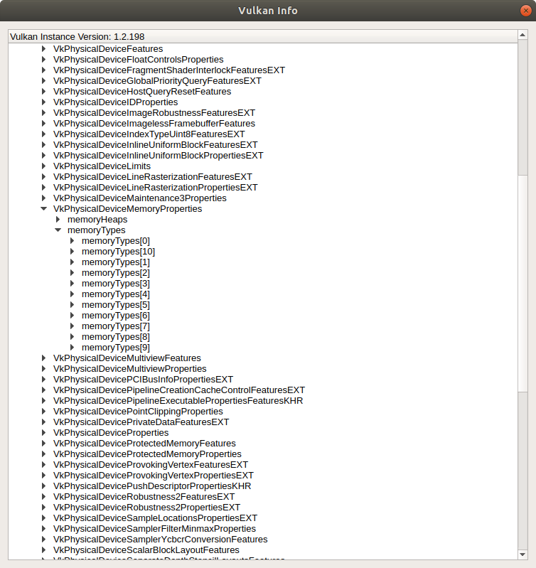
NOTE: There can be many types with similar characteristics, and for the types with identical properties, the memory with the better performance is placed before. That’s why it is recommended to traverse the list from the beginning when searching for the appropriate memory type.
According to the rising bits, our buffer can use a memory type under the index 0th, 7th, 8th, 9th, or 10th. Let’s unfold the list to see the properties:

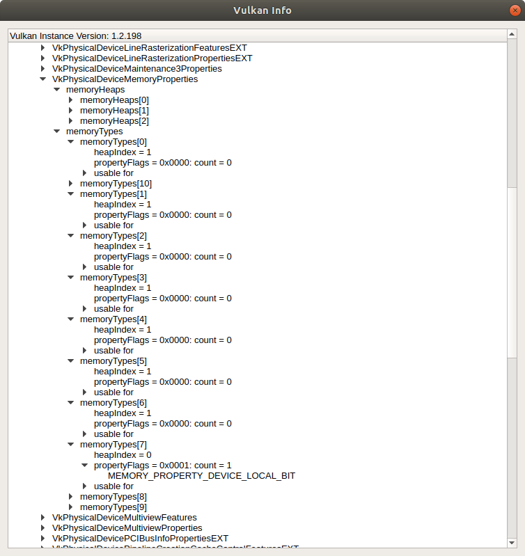
To find the memory type for the buffer, we need to observe property flags for each type. Recall that we wanted our control points buffer to be device local (gpu_allocator::MemoryLocation::GpuOnly). The gpu_allocator crate internally uses the ash::vk::MemoryPropertyFlags::DEVICE_LOCAL flag when searching for the appropriate memory type index. From the picture, we see that the very first type doesn’t support that flag, as well as the next 6 types. But the 7th type has the flag MEMORY_PROPERTY_DEVICE_LOCAL_BIT set. Now, hopefully, we understand where this number comes from.
The selected memory type struct itself has the following fields:
MemoryType {
    propertyFlags: MEMORY_PROPERTY_DEVICE_LOCAL_BIT,
    heapIndex: 0,
}
The heapIndex field points to the memory heap. Similar to the memory types, we can get memory heaps programmatically, but we’ll use the vkconfig tool again. My GPU has 3 heaps:

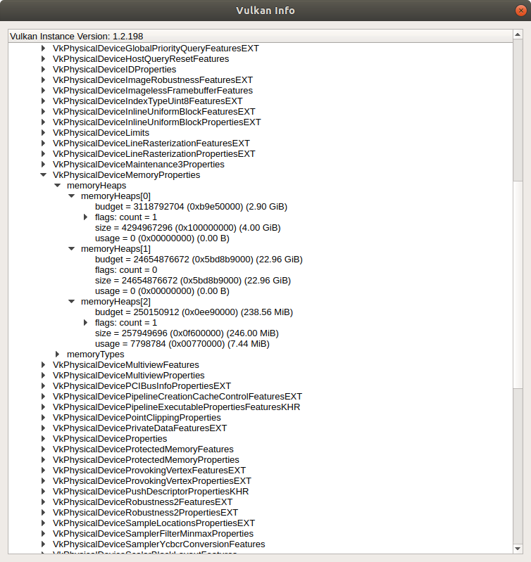
That looks correct - the heap under the index 0 points to the GPU memory, which indeed has 4Gb of memory. The other two are a system memory and a fast device memory that is CPU-visible (and the one that was used for the staging buffer).
Do you now see how exactly low-level Vulkan is?
Index buffer
Though there are no more buffer declarations in the vertex shader, there’s still a buffer that is used explicitly. Let’s look closely at this line in the shader:
ControlPoint cp = controlPointBuffer.data[gl_VertexIndex];
This gl_VertexIndex - what is it, and where does it come from? Well, looking at the variable name, it should be clear that it is a build-in input variable that holds an integer index for the vertex. And the value depends on how the draw call was initiated. For example, if we call the draw function like this:
device.cmd_draw(command_buffer, vertex_count, ...);
we tell the API to draw a vertex_count number of vertices, and gl_VertexIndex will be the index from this count.
But if we look at the teapot_data, we find a vector patches. Each entry in that vector is an index pointing to a control point in the control_points vector. We need this to reduce vertex (control point to be more precise) data. If you recall, the original data doesn’t cover a full teapot shell but some part of it. For example, the body part represents only a quarter of a full surface. Additionally, adjacent patches share the same control points. If we would not use the indices, we’d have to copy each point multiple times. And each point is a 3-component vector (with x, y, z components). Instead, we use only a single 2-byte index to point to the identical data. We call a draw command like this:
device.cmd_draw_indexed(command_buffer, index_count, ...);
with a bound index buffer (more about binding later).
Since in our case the index data is static, we use the same create_buffer::create_gpu_buffer_init function as for the control points buffer. This time we specify the usage as ash::vk::BufferUsageFlags::INDEX_BUFFER and the buffer will be read (ash::vk::AccessFlags::INDEX_READ) in the ash::vk::PipelineStageFlags::VERTEX_INPUT stage.
Let’s see what the allocator library created:
pub struct Allocation {
    ...
    offset: 1536, // offset in VkDeviceMemory object to the beginning of this allocation, in bytes
    size: 1024, // size of this allocation, in bytes
    memory_type_index: 7, // memory type index that this allocation was allocated from
    device_memory: 0x0000100000000010, // handle to a Vulkan memory object
    mapped_ptr: None, // mapped pointer to the beginning of this allocation
}
The requested size is 896 bytes, the actual size of the allocated memory is 1024. Offset 1536 says that the buffer is placed not at the beginning of the allocated memory. Recall that the control point buffer takes 1536 bytes. The allocator allocates one big memory chunk and binds different objects to different offsets in this chunk. It’s recommended to have as few allocations as possible. There’s even a limitation to the number of allocations - the Specification guarantees only 4096. My GPU allows more - 4294967295 allocations total.
There are no bound resources in the tessellation control shader, and we don’t need to create any resources for that stage. There’s a push constant, but that’s different - we don’t need to allocate any memory for that. Push constants will be discussed later.
Patch instance buffer
Next one is the tessellation evaluation shader. This time there’re 2 buffers bound to this stage.
The first buffer holds color and a matrix per patch. This data is static and we use the same vulkan_utils::create_gpu_buffer_init function as before. I called this buffer instances buffer. It’s a storage buffer (ash::vk::BufferUsageFlags::STORAGE_BUFFER) that will be read (ash::vk::AccessFlags::SHADER_READ) in the tesselation evaluation shader (ash::vk::PipelineStageFlags::TESSELLATION_EVALUATION_SHADER).
The allocation info for the buffer is:
pub struct Allocation {
    ...
    offset: 2560, // offset in VkDeviceMemory object to the beginning of this allocation, in bytes
    size: 2304, // size of this allocation, in bytes
    memory_type_index: 7, // memory type index that this allocation was allocated from
    device_memory: 0x0000100000000010, // handle to a Vulkan memory object
    mapped_ptr: None, // mapped pointer to the beginning of this allocation
}
Requested size - 2240 bytes, allocated size - 2304 bytes. The memory for this buffer lives in the same allocation as the previous two buffers. Control points buffer is 1536 bytes, index buffer is 1024 bytes, hence 1536 + 1024 = 2560 bytes offset.
Uniform buffer
This time we have a dynamic buffer. I.e., the data inside it is not persistent and will be changing from frame to frame. It could be a storage buffer as well, but since it holds only a single matrix, we are sure that we’ll fit in memory space limits. Additionally, on some GPUs accessing this type of memory can be faster.
NOTE: The Specification guarantees
maxUniformBufferRangeat least 16384 bytes, whereasmaxStorageBufferRangeis 2e27 bytes.
Here’s a snippet of how to create the buffer with vulkan_utils::create_buffer function:
let mut mem_buffers = Vec::with_capacity(crate::CONCURRENT_RESOURCE_COUNT as usize);
for i in 0..crate::CONCURRENT_RESOURCE_COUNT {
    let mem_buffer = vulkan_utils::create_buffer(
        ...
        vk::BufferUsageFlags::UNIFORM_BUFFER,
        gpu_allocator::MemoryLocation::CpuToGpu,
        ...
    )?;

    mem_buffers.push(mem_buffer);
}
We don’t need to initialize the buffer with data this time. We’ll do it every frame just before the rendering. Here we want a uniform buffer (ash::vk::BufferUsageFlags::UNIFORM_BUFFER), accessible both by CPU and GPU (gpu_allocator::MemoryLocation::CpuToGpu). The allocator crate will map the memory so we can access its pointer at any time. But wait, why do we create buffers in a loop? What is this crate::CONCURRENT_RESOURCE_COUNT?
Let’s look at what can happen when we render multiple frames in a row. Before, I wrote that a CPU and a GPU are not synchronized in any way by default. When we submit a bunch of commands on a CPU, we don’t know when a GPU will start to execute these commands, and we don’t know when it will finish.
Now imagine, in the very first frame, we wrote data into our mapped uniform buffer, then submitted a work that uses that buffer. According to § 7.9. Host Write Ordering Guarantees of the Specification:
When batches of command buffers are submitted to a queue via a queue submission command, it defines a memory dependency with prior host operations, and execution of command buffers submitted to the queue.
That means that if we wrote to a buffer on the host before a submit command, Vulkan takes care of synchronization automatically. That is one of the rare cases of implicit synchronization. Because of that, in the first frame, the GPU will see the valid data, and all is fine.
Now we’re going to render a second frame. Remember that we don’t know if GPU finished or not, there’s no implicit synchronization for this case, and if we use the same uniform buffer we used in frame 1, we can end up writing to the buffer that the GPU uses right now (i.e., reads). Sounds like a race condition and undefined behavior. What can we do? Well, we can wait on the host until the device finishes like we did after we copied the staging buffer with ash::Device::queue_wait_idle. But that’s not good - we’ll wait on the CPU doing nothing. What we can do instead is to create another buffer where we can safely write. Now we proceed to frame 3. We may think that the GPU finished with frame 1, and we can use the first buffer again. But that’s not true - there’s no implicit synchronization, and we don’t know if GPU finished or not. We can have a very fast processor and a very old and slow GPU where we submit heavy work so that the CPU can record hundreds of frame jobs before the device completes only one. We can, of course, create more buffers, but we’ll go the other way. We’ll use 2 buffers, and we’ll synchronize explicitly - together with a buffer, we’ll submit a special object - a Fence. With it, we can find out the status of our work previously.
Now our render cycle will look like this:
- Frame A: look at
fence1and, if needed, wait untiljob1is completed, updatebuffer1, submitbuffer1andfence1. - Frame B: look at
fence2and, if needed, wait untiljob2is completed, updatebuffer2, submitbuffer2andfence2. - Repeat.
The number of interleaving buffers (2) is stored in a global constant crate::CONCURRENT_RESOURCE_COUNT. It will be used a couple more times.
For 2 uniform buffers, the allocations look like this on my machine:
pub struct Allocation {
    ...
    offset: 0, // offset in VkDeviceMemory object to the beginning of this allocation, in bytes
    size: 256, // size of this allocation, in bytes
    memory_type_index: 10, // memory type index that this allocation was allocated from
    device_memory: 0x0000563a848b2c80, // handle to a Vulkan memory object
    mapped_ptr: Some(0x00007f9ebc517000), // mapped pointer to the beginning of this allocation
}
pub struct Allocation {
    ...
    offset: 256, // offset in VkDeviceMemory object to the beginning of this allocation, in bytes
    size: 256, // size of this allocation, in bytes
    memory_type_index: 10, // memory type index that this allocation was allocated from
    device_memory: 0x0000563a848b2c80, // handle to a Vulkan memory object
    mapped_ptr: Some(0x00007f9ebc517000), // mapped pointer to the beginning of this allocation
}
The requested size for each buffer is 64 bytes (size of a single matrix), but the allocated size is 256. What a waste of space! It would be better to have a single buffer 64 * 2 bytes size and change offsets every frame before writing the data. But we’ll not do this for this application. Notice how the library uses the same memory chunk but allocates a piece of it with the offset for the second buffer. Also, the memory type index is different this time and points to:
MemoryType {MEMORY_PROPERTY_DEVICE_LOCAL_BIT
    property_flags: VK_MEMORY_PROPERTY_HOST_VISIBLE_BIT | VK_MEMORY_PROPERTY_HOST_CACHED_BIT | VK_MEMORY_PROPERTY_HOST_COHERENT_BIT,
    heap_index: 1,
}
Looks correct - we asked for a host-visible memory since we’re going to update the buffer every frame. The heap under the index 1:
MemoryHeap {
    size: 24654882816,
    flags: 0,
}
The ~23Gb size tells us that this is system memory. On my machine, I have 30Gb. Also, notice that the allocations mapped_ptr is not None - the gpu-allocator crate maps a host-visible memory as soon as it’s created.
The fragment doesn’t have any bound resources.
Clean
As usual, we don’t forget to destroy Vulkan objects and free memory. In the clean function, for every created buffer we need to destroy a buffer object with the ash::Device::destroy_buffer function and free an allocation with gpu_allocator::Allocator::free function. It is important to do it before destroying the allocator itself, which we do in the vulkan_base::clean function.
What next
We created a lot of resources today. But if we’ll launch the program, we’ll see the same empty window again. Though we uploaded the data on the GPU, we didn’t say how to use it. We need to tell the device which resource goes to which slot. We’ll do this next time.
The source code for this step is here.
You can subscribe to my Twitter account to be notified when the new post is out or for comments and suggestions. If you found a bug, please raise an issue. If you have a question, you can start a discussion here.