In the previous step we uploaded the data to the GPU, but we still don’t know how to use it. Today we’ll fill that gap partially. We need to tell Vulkan upfront which resources we’re going to use for a particular effect. We do it via pipelines.
- Introduction
- Shaders
- Resources
- Pipelines
- Swapchain
- Drawing
- Depth Buffer
Let’s look again at the shaders layout:

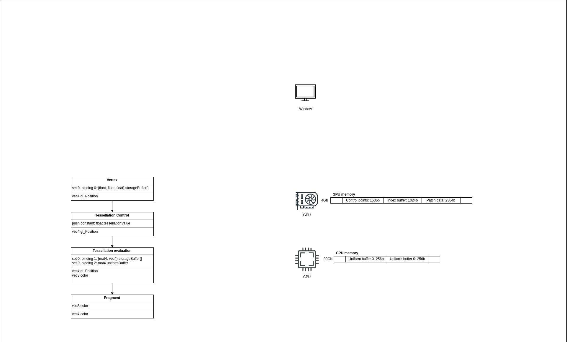
Let’s look at the buffer’s declaration, namely, at the set and binding. It would be nice to have just a slot and at runtime just say: “hey API, I want to set my vertex buffer to slot number 0”. But Vulkan would not be Vulkan if it was so easy. Because of the broad architectures range of Vulkan conformant devices, it was decided to use a binding model that will work everywhere. And this binding model consists of descriptors that are organized in sets. Imagine that some device has a special memory where it holds a table with indices to resources. Since this memory is limited, it’s not possible to have a lot of tables (sets), and the size of these tables is also limited.
NOTE: The Specification guarantees at least 4 sets (
VkPhysicalDeviceLimits::maxBoundDescriptorSets) and 128 resources per stage (VkPhysicalDeviceLimits::maxPerStageResources). On myNVidia Quadro P1000, the maximum number of sets is 32, and the maximum number of resources is 4294967295.
Let’s find out how and where we declare these sets.
Descriptor set layout
We need to navigate to the teapot workspace, where we continue initializing the main data structure. We declare sets in the teapot::create_descriptor_set_layout function. Here we fill different ash::vk::DescriptorSetLayoutBinding structures, which we pass with the ash::vk::DescriptorSetLayoutCreateInfo structure to the ash::Device::create_descriptor_set_layout function.
It’s recommended to split sets by update frequency, which I didn’t do in the application. Updating a set has some cost, and if it’s possible to avoid such an update better not to do it. Since we have a very limited number of resources, I decided to keep everything in one set. For example, one set can be reserved for constant data that is rare or never changed, such as a projection matrix. Another set can be used with per-frame updated resources, such as view matrix. Finally, another set is - for per draw updated data, a model matrix, for example. When we need to update a descriptor set, we batch descriptors and submit everything in one go. In our example, we have only one set and bind the buffers as follows:
- Control points buffer - slot 0 of the vertex shader.
- Patch data buffer - slot 1 of the tesselation evaluation shader.
- Uniform buffer - slot 2 of the tesselation evaluation shader.
Notice that the set is a sort of a global structure. Although we need to specify a shader stage, we can’t bind a resource to the same slot in different shaders. That is what we’ll get if we’ll try to bind the control points buffer to slot 1 in the vertex shader with the validation layers enabled:
Validation Error: duplicated binding number in VkDescriptorSetLayoutBinding. The Vulkan spec states: The VkDescriptorSetLayoutBinding::binding members of the elements of the pBindings array must each have different values
Also, notice that we don’t specify the actual data when creating a layout. The analogy to the descriptor set layout would be a function declaration in C/C++. When we declare a function foo(int), we tell the type of the argument, the value itself we’ll pass later when we’ll call that function. The same is here - we just tell the API our intentions so the driver can check the correctness.
Now, when we have a descriptor set layout, how do we use it in Vulkan? We do it through a structure ash::vk::PipelineLayout, which in turn, we provide through another structure when creating a pipeline. So let’s first understand what is a pipeline.
Pipelines
Simply put - a pipeline holds the state of a draw call. In the application, we use two different pipelines - one for solid rendering and another for wireframe rendering. It’s not possible to create a single pipeline for these two different drawing methods since every method requires a GPU state change. Changing a state is very tricky to do at runtime, so Vulkan went another way - everything should be declared upfront. There’re some exceptions to these rules, and some states are allowed to be changed at a draw time. We’ll see that shortly. We create pipelines in the teapot::create_pipelines function. That’s quite a lengthy procedure. Scroll down to the place where ash::vk::GraphicsPipelineCreateInfo for the solid pipeline is instantiated, we’ll walk through all the states we need.
-
flags(ash::vk::PipelineCreateFlags::ALLOW_DERIVATIVES)- creating a pipeline means compiling shaders, doing lots of checks. But if we have multiple similar pipelines, we can speed up the creation of the following objects. The flagash::vk::PipelineCreateFlags::ALLOW_DERIVATIVEmarks a pipeline as parent. We create a pipeline for solid rendering first, and based on it, we create a second pipeline. -
stages(&stages)- list of shaders stages with shader modules and entry function names. We have 4 stages withmainentry in all of them. Every stage is kept inash::vk::PipelineShaderStageCreateInfostructure. Here we specify a shader stage, a shader module, and an entry function name. -
input_assembly_state(&ia_state)- we need to specify the topology for the model we’re going to render with the pipeline. In our case this isash::vk::PrimitiveTopology::PATCH_LIST, which we pass in aash::vk::PipelineInputAssemblyStateCreateInfostructure. -
rasterization_state(&raster_state)- describes how geometry should be rasterized. In theash::vk::PipelineRasterizationStateCreateInfostructure, we set a polygon mode asash::vk::PolygonMode::FILL- we want solid triangles filled with color, cull mode asash::vk::CullModeFlags::BACK- we want to cull the back faces, i.e., not to render a triangle if it looks away. To find if a face is looking back or forward, we specify a front face vertices order -ash::vk::FrontFace::CLOCKWISE. The line width is not necessary when rendering a solid triangle, but it’s necessary when rendering in a wireframe mode, which we’ll see shortly. -
color_blend_state(&col_blend_state)- in the application we render only opaque triangles. That means we don’t need any blending. Also, we need to specify a write mask, i.e., which color components should be written. This info we provide in aash::vk::PipelineColorBlendAttachmentStatestructure. The color blend state needs to be specified per render target. Since we’ll use a single target (a window surface), this single state we store in aash::vk::PipelineColorBlendStateCreateInfostructure.
NOTE: Once I spent a good hour trying to understand why I have a black screen. It turned out that I forgot to specify this mask, and by default, it’s 0, i.e. don’t save anything. As you can see - this is not an error, so the validation layers were silent.
dynamic_state(&dyn_state)- the dynamic states we talked above. In the application, I decided to resize the window freely. Resizing a surface would mean a state change. If there would no dynamic states, or we omit them, we would have to create a new pipeline every time we change the window size. Luckily for us, we can mark the statesash::vk::DynamicState::VIEWPORTandash::vk::DynamicState::SCISSORas dynamic. That means that now we have to set these states every time before rendering. But still, I found this simpler than the new pipeline after the change.
NOTE: There’re many other dynamic states.
viewport_state(&viewport_state)- although we specified that the viewport and scissor are dynamic we still need to provide the state in aash::vk::PipelineViewportStateCreateInfostructure. At least with default values. If we’ll not do this we’ll get an error:
Validation Error: Rasterization is enabled, but pCreateInfos[0].pViewportState (=NULL) is not a valid pointer. The Vulkan spec states: If the rasterizerDiscardEnable member of pRasterizationState is VK_FALSE, pViewportState must be a valid pointer to a valid VkPipelineViewportStateCreateInfo structure.
-
layout(pipeline_layout)- this is the pipeline layout we talked about. It shouldn’t be confused with the descriptor set layout we created at the beginning. We create one in the teapot::create_pipeline_layout function. And this is the place where we provide the aforementioned descriptor set layout. Recall that we decided to use only one set hence there’s only one entry in thelayoutsarray. That will be our set number 0, which we can see in the shaders. The single set with multiple bindings. Also, you probably noticed theash::vk::PushConstantRangestructure usage inash::vk::PipelineLayoutCreateInfo. A small amount of data can be written directly in a command buffer, and before rendering a frame, it will be copied to GPU registers. How small should it be? The Specification guarantees at least 128 bytes (VkPhysicalDeviceLimits::maxPushConstantsSize). Of course, the actual size depends on the hardware. The best practice regarding the push constant usage would be to reduce its usage (a single 4-byte number or maybe a 4 component vector are ok) or not to use them at all and provide data in uniform buffers. If there’s no more space to keep a push constant in registers, it will be copied to the memory, and that is a slow operation. If you have something to add, please drop a message in the GitHub discussion to that post (the link at the bottom). Nevertheless, we’ll use the push constant here for the tesselation factor. Since these 128 bytes (or more) are reserved for the entire pipeline, we need to provide a size and an offset together with a shader stage. In our case, the only stage that uses the push constant isash::vk::ShaderStageFlags::TESSELLATION_CONTROL. Let’s imagine that we need another 2 floats constant in the fragment shader - in that case, we need anotherash::vk::PushConstantRangestructure where the stage flag would beash::vk::ShaderStageFlags::FRAGMENT, the size - 8 bytes and the offset - 4 bytes (because the first 4 bytes reserved by the tesselation factor). -
render_pass(render_pass)- inVulkan, the rendering is organized in render passes. If you want to draw something, you have to start a render pass and draw inside it. The render passes themselves are organized in subpasses. The concept of render passes mostly relates to a mobile world where the GPU architecture differs from desktop GPUs. Probably you heard about tiled architectures - to avoid costly memory operations, the render area is split on independent tiles. The size of one tile is selected such that it can fit in fast on-chip memory. Let’s look at how a depth test can be handled on a tiled architecture. When we draw a new fragment, we need to read the current depth from the depth buffer and compare it with the new. If the new “wins” we have to write it to the buffer. After we’re done, we can either save the depth buffer for further usage or ignore it. I marked bold the memory requests, and as you can see, there’re multiple of them, and they are considered expensive operations. But if this memory is a special fast-tile-on-chip-memory, then we can reduce the costs of reading and writing to the main memory or avoid them completely if we ignore the final store operation. Interesting to know that when we process a tile, we can’t get any information from neighbor tiles because they do not exist. That limits some operations, but we’ll not see this in our application. In render passes, we define which attachments are used in which subpasses. Another word for attachment is render target.Vulkanimplicitly sets dependency barriers between attachments. It is important to understand that the same effect can be achieved with multiple subpasses inside a single render pass or multiple render passes with a single subpass each. In the second case, we’d need to set barriers manually, and probably it will be slower on mobile (on desktop, it mostly makes no difference, but it depends on a GPU, of course). In our application, we have only one render pass with a single subpass. We create it in teapot::create_render_pass function. Here we define a single attachment - the surface we’ll render into. We set the following properties for it:formatthat we selected when got the physical device.- number of
samples- 1 in our case. load_op = ash::vk::AttachmentLoadOp::CLEAR- when we begin to work with the memory, we want to clear it to some value. On tiled GPU, the tile-memory will be initialized with that value, and no main memory will be involved.store_op = ash::vk::AttachmentStoreOp::STORE- when we finish, we want to keep the memory so the information from it can be displayed on a monitor. On tiled GPUs, the complete tile memory will be copied to the main memory.stencil_load_op = ash::vk::AttachmentLoadOp::DONT_CAREandstencil_store_op = ash::vk::AttachmentStoreOp::DONT_CARE- we’re not using stencils in the application.stencil_store_op = ash::vk::AttachmentStoreOp::DONT_CAREinitial_layout = ash::vk::ImageLayout::UNDEFINED- to set implicit barriers, the runtime has to know the layout of an attachment so it can transition between different layouts safely. In our application, we don’t care about the layout at the beginning of the render pass…final_layout = ash::vk::ImageLayout::PRESENT_SRC_KHR- …but we care about the final layout so the memory can be transitioned to the format appropriate for the presenting.
The defined attachment we provide in a
ash::vk::AttachmentReferencestructure as a reference to aash::vk::SubpassDescriptionstructure, which is passed further toash::vk::RenderPassCreateInfo. This structure has adependenciesfield, which we need to set if we have multiple subpasses. Even with a single subpass, we need to provide a dependency before the subpass and after the subpass. LuckilyVulkanset this kind of dependencies (calledVK_SUBPASS_EXTERNALdependencies) implicitly. The render pass itself we create by calling theash::Device::create_render_passfunction. -
subpass(0)- yes, we need a pipeline for every subpass (of course, if it differs). -
multisample_state(&multisample_state)- the app doesn’t use multisample, but we still need to set the sample count (1 in our case) with aash::vk::PipelineMultisampleStateCreateInfostructure. -
tessellation_state(&tessellation_state)- we’re using tessellation, so we have to set this state. Inash::vk::PipelineTessellationStateCreateInfowe tell how many control points we want per patch (16 in our case). -
vertex_input_state(&vert_inp_state)- recall that we provide the vertex data as a storage buffer and not as a vertex buffer. Because of that, we’re not interested in the vertex input, but we still have to set a default one with aash::vk::PipelineVertexInputStateCreateInfostructure. If we don’t do this, we’ll get:
Validation Error: Invalid Pipeline CreateInfo[0] State: Missing pVertexInputState. The Vulkan spec states: If pStages includes a vertex shader stage, pVertexInputState must be a valid pointer to a valid VkPipelineVertexInputStateCreateInfo structure
With the fully prepared ash::vk::GraphicsPipelineCreateInfo struct, we can build the solid pipeline. But recall, we want another pipeline to draw a wireframe. These two pipelines are very similar because they share the same shaders and the majority of the states. The only different state is the rasterization state which should have the following parameters:
polygon_modeis nowash::vk::PolygonMode::LINE.cull_modeis nowash::vk::CullModeFlags::NONEbecause we want to see wireframes even for back-facing triangles.front_face-ash::vk::FrontFace::CLOCKWISE, as before, but since we’re not culling, it can be anything.line_width- should be 1.0 this time. For the width other than 1.0, the special feature (ash::vk::PhysicalDeviceFeatures::wide_lines) should be supported and enabled.
Additionally, we need to modify the ash::vk::GraphicsPipelineCreateInfo struct:
flagsis nowvk::PipelineCreateFlags::DERIVATIVEbecause this is a child pipeline.base_pipeline_index- we’ll provide both info structs in a create function. Since the wireframe pipeline is a child pipeline, it should point to its parent. The index 0 tells the API to derive from the first pipeline in the list, which we’ll create shortly.
All other information can be copied from the previous pipeline info.
With the two structs ready, we pass them in a list to the ash::Device::create_graphics_pipelines function (notice the plural in the functions name), and if everything was ok, it gives us a list of created pipelines.
It’s important to remember that we didn’t specify the actual resources yet. We just declared the types of resources we want to use in the future with these pipelines. We don’t have any images, but we still created a render pass where we described the render target.
Clean
As usual, we destroy everything we created so far in the teapot::clean function - descriptor set layout, pipeline layout, render pass, and pipelines.
What next
We have shaders, have buffers filled with the data, have instructions for the GPU where to read the data from and the type of the data. But if we run the app, we’ll see the same empty window. This is because we didn’t set the correct data to the correct slot, didn’t tell GPU to start rendering. But there’s another important thing we didn’t touch so far. Although we discussed the surface when we selected a physical device (recall surface format, present mode), we didn’t create anything where we could render. A surface is an abstraction, it doesn’t own memory. In the next step, we’ll create a so-called swapchain - a set of images that the presentation engine will use to present in the window.
The source code for this step is here.
You can subscribe to my Twitter account to be notified when the new post is out or for comments and suggestions. If you found a bug, please raise an issue. If you have a question, you can start a discussion here.